02 / HARDWARE + LAB

THEPHYSICALLAYER.

NOTE 01 / OPERATORI enjoy the part of computing that can be touched, opened, repaired and understood.

NOTE 02 / SCOPEServers, networking equipment, thermals, electronics and physical infrastructure are as interesting to me as the software running on top of them.

LOGIC BUS
5V
POWER PATH
IDLE
RELAY STATE
OPEN
THERMAL PATH
NOMINAL
SYSTEM STATE
STANDBY

SERVERS · NETWORKING · REPAIR · THERMALS · ELECTRONICS

00 LOGICDecisions at signal level

SYSTEMS START BELOW THE SOFTWARE.

HP-01

COMPUTE

  • Enterprise servers
  • Custom systems
  • CPU platforms
  • Memory / storage
HP-02

NETWORK

  • Firewalls
  • Switches / NICs
  • VLAN infrastructure
  • Management interfaces
HP-03

THERMALS

  • Airflow
  • Fan replacement
  • Temperature monitoring
  • Noise reduction
HP-04

REPAIR

  • Diagnostics
  • CPU socket repair
  • Component replacement
  • Hardware recovery
HP-05

MAKER

  • 3D printing
  • Electronics
  • Custom enclosures
  • RelayDynamics hardware
CASE 01 / SERVICE LOG

HP PROLIANT
DL380 RECOVERY

DAMAGED CPU SOCKET / RESTORED OPERATION

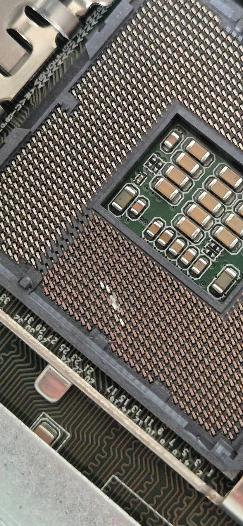
Close view of the damaged CPU socket in the HP ProLiant DL380
FAULT DETAIL / CPU SOCKET 02AUTHENTIC REPAIR IMAGE

A server with bent socket pins was inspected, repaired and returned to functional dual-CPU operation.

FAULT
Bent CPU socket pins
PROCESS
Inspection
Manual alignment
Validation
RESULT
CPU functionality restored

IF IT CAN BE OPENED, IT CAN PROBABLY BE UNDERSTOOD.

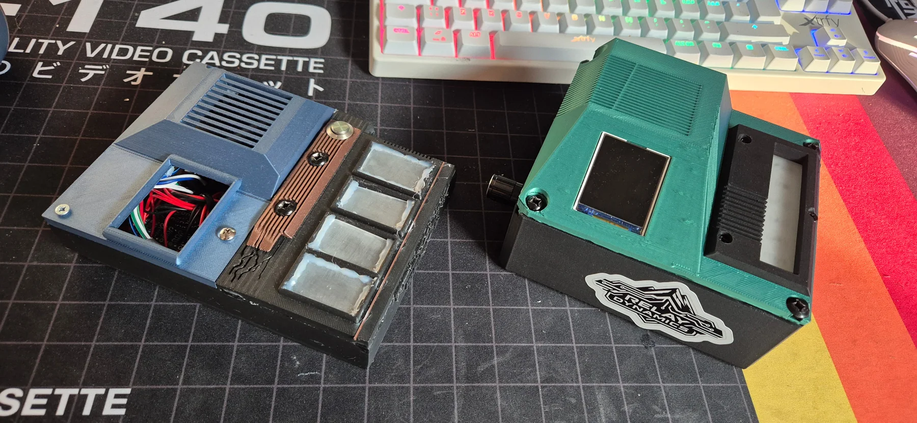
CASE 02 / RELAYDYNAMICS

RELAYLINK
MARK I → II

PHYSICAL BUILDS / PROTOTYPING

RelayLink Mark I and Mark II physical prototypes on a workbench
BUILD COMPARISON / MARK I + MARK IIWORKING PROTOTYPES

A physical control interface developed through successive working builds—combining enclosure design, electronics, assembly and software.

VIEW RELAYLINK MARK II REPOSITORY
PROJECT
RelayLink Mark II
METHOD
3D printing
Assembly
Electronics
STATUS
Working build
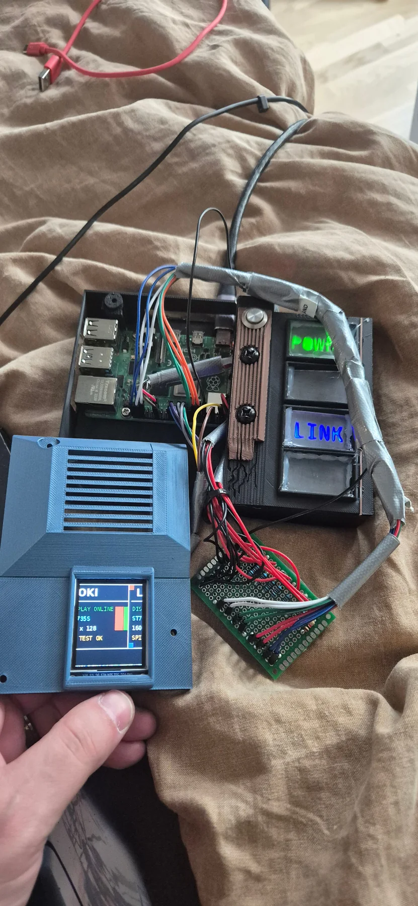
Early RelayLink Mark I prototype with exposed wiring
MK-I / FUNCTIONAL PROTOTYPE
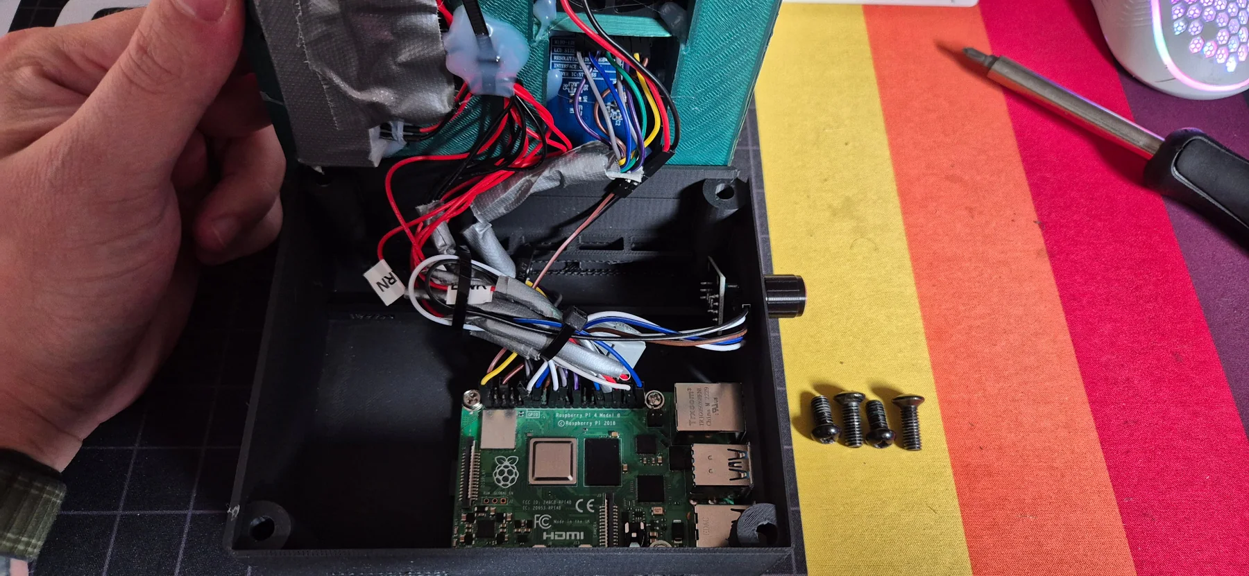
RelayLink internal assembly showing Raspberry Pi and wiring
MK-II / INTERNAL ASSEMBLY

MEASURE BEFORE ASSUMING.

CASE 03 / TEST INSTRUMENT

MOTHERBOARD
MEASUREMENT RIG

LIVE SYSTEM / PHYSICAL TELEMETRY

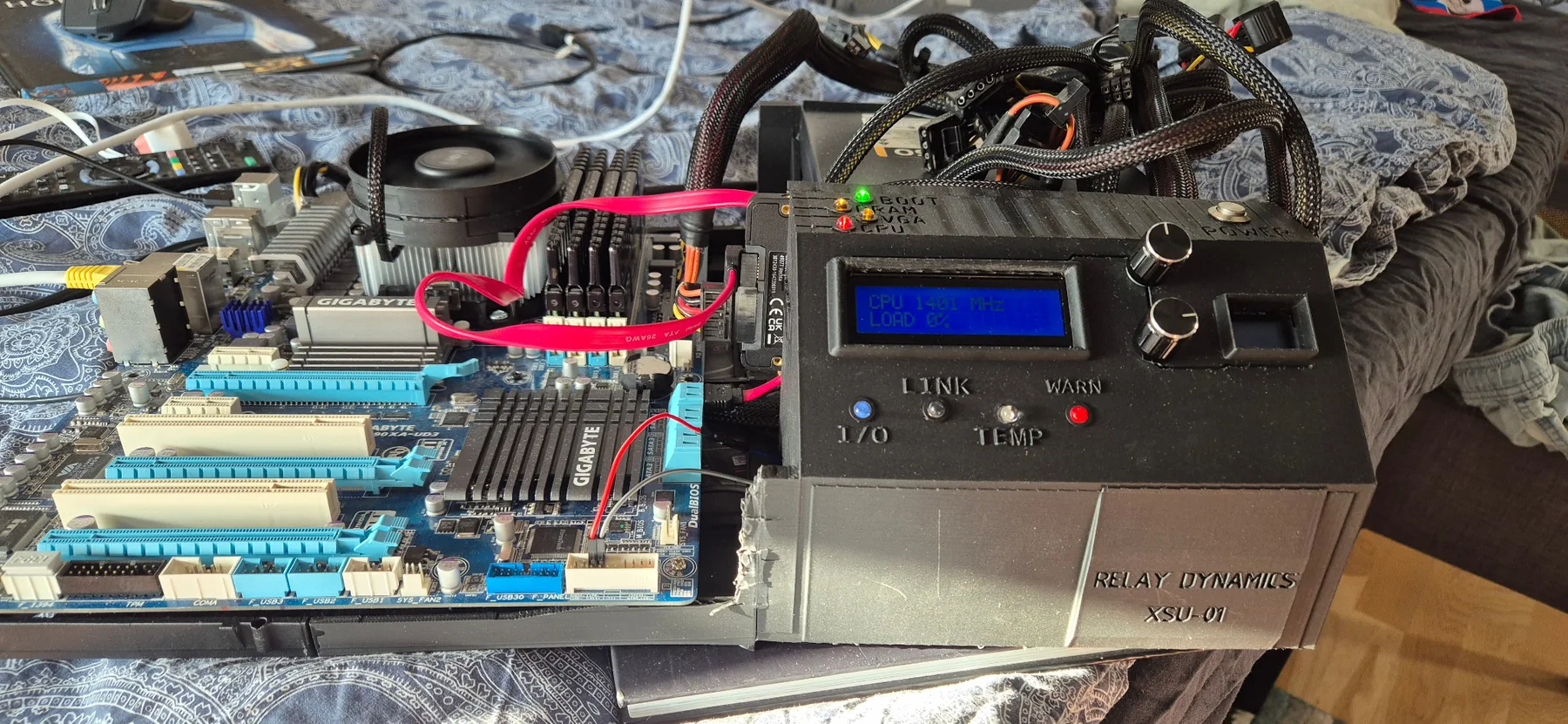
Running motherboard connected to a custom 3D-printed measurement control panel
BENCH TEST / LIVE MOTHERBOARDFUNCTIONAL EXPERIMENT

A 3D-printed control panel assembled to observe and take measurements from a motherboard while it was running.

BUILD
Custom enclosure
Control interface
PURPOSE
Live measurement
System observation
METHOD
3D printing
Electronics
Assembly
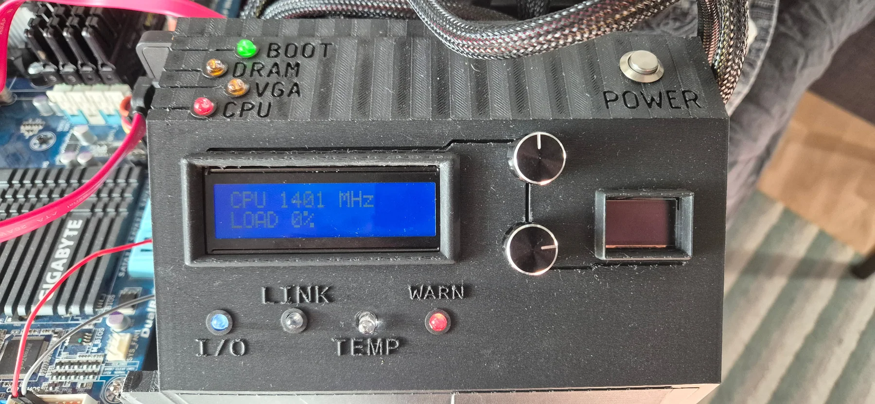
Close-up of the 3D-printed motherboard measurement control panel
CONTROL PANEL / LIVE READOUT
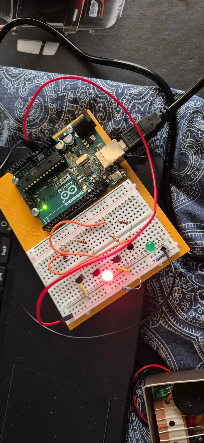
Breadboard experiment using discrete transistors, resistors and indicator LEDs
DISCRETE TRANSISTOR LOGIC / BREADBOARD TEST

CIRCUIT NOTEThe photo shows a transistor-based logic experiment, but the exact gate or latch topology cannot be verified without tracing the connections or seeing the schematic.

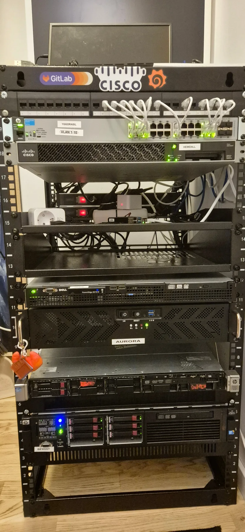
Front view of Vincent's physical homelab rack with networking and compute equipment
RELAY NETWORK / PHYSICAL PLANTSWEDEN · 2026
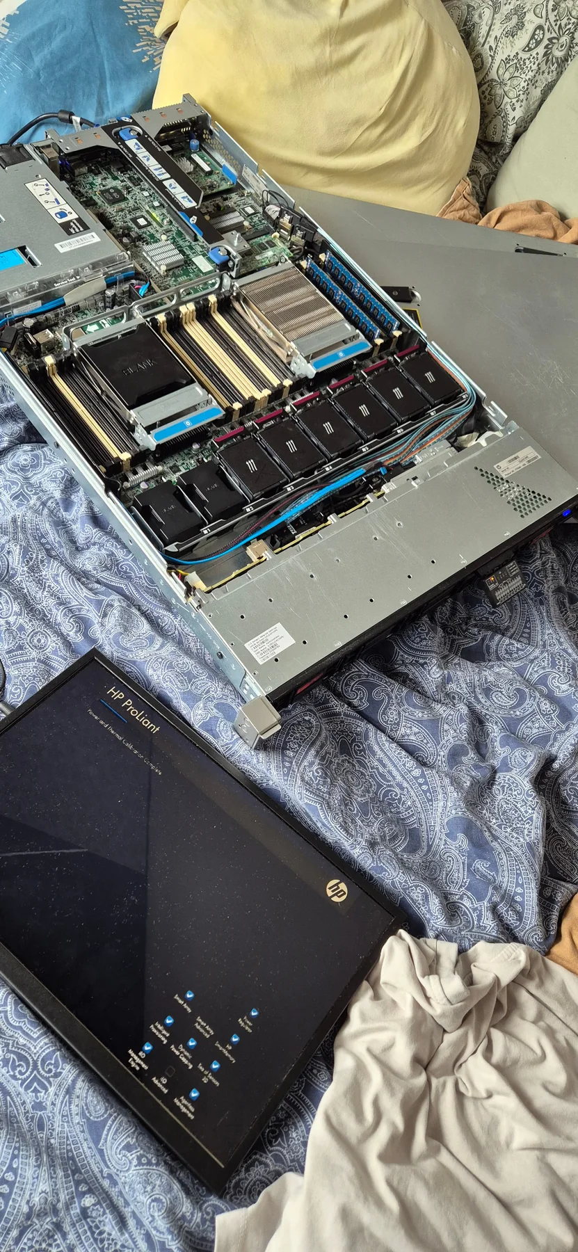
Open HP ProLiant DL360 G8 Atlas node during hands-on inspection
ATLAS / DL360 G8OPEN CHASSIS / DOCUMENTARY VIEW
RACK / 20UPOWER + DATA
U19

YGGDRASIL

SWITCHING

U18

HEIMDALL

FIREWALL

U13

ODEN

COMPUTE / SERVICES

U11

AURORA

COMPUTE / VIRTUALIZATION

U09

BIFROST

ENTERPRISE COMPUTE

U07

LOKI

EDGE SERVICES

U06

ATLAS

ENTERPRISE COMPUTE / DL360 G8

PHYSICAL LINKS SHOWN / INTERNAL ADDRESSES OMITTED
02.3 / WHY HARDWARE

SOFTWARE MAKES MORE SENSE
WHEN YOU UNDERSTAND
THE MACHINE BELOW IT.

I like knowing what happens beneath the abstraction: power, thermals, memory, storage, networking and the physical constraints software ultimately depends on.
01REPAIR RATHER THAN REPLACE.

02MEASURE BEFORE ASSUMING.

03FAILURE IS DIAGNOSTIC INFORMATION.

04PROTOTYPE. TEST. REBUILD.

05COMBINE SOFTWARE AND HARDWARE.

RELAYDYNAMICS / PHYSICAL SYSTEMS / BUILD STATUS: ACTIVE